
Your model already understands parameters. Now you need to learn something just as important: recognize physical regions even if the length, mesh and internal numbers change that MAPDL assigns to nodes and elements.
YOUR MISSION
You will build five named regions: the fixed end, the tip, the top face, the top edge of the tip and a central band of elements. You will then modify the beam and you'll see that they all still exist without typing a single ID.
Guiding Question How do you program a physical region when you don't know its node numbers yet?
Objectives
By completing M02 you will be able to demonstrate that:
- You distinguish entities from the solid model and the finite element model.
- Explain why a selection is a temporary state and a component is a persistent reference.
- You combine sets by
S,A,RandU. - You select nodes by location and elements by position of their centroid.
- You explicitly control tolerance by
SELTOL. - You use a local system as a mobile reference linked to the tip.
- Audits components with
*GET,COUNTand relationships between counts. - You retrieve the complete model before continuing through
ALLSEL,ALL.
Prerequisites and files
- Have completed M01 or understand parameters, expressions and checks with
*IF. - Recognize that the beam occupies
0 ≤ X ≤ beam_l,0 ≤ Y ≤ beam_hand0 ≤ Z ≤ beam_b. - Keep the system consistent SI: meters, newtons and pascals.
02_start.macStarting point.02_geometry_selections.mac— guided solution and audit.02_bug_hunt.mac— five deliberate defects.02_challenge.mac— challenge template.02_expected_results.csv— self-correction contract.
How to use this lesson
| Route | Duration | Stroke |
|---|---|---|
| First win | 30–35 min | Prediction, parametric geometry and first components audited. |
| Complete | 70–75 min | In addition, intersections, executable contract, bug hunting and challenge. |
Recommendation: Think of each region as a whole before writing NSEL. If you can't predict how many entities will capture a selection, you still don't understand it.
Session map
- Mission: objectives, downloads and prediction on regions.
- Mental models selection as state and set algebra.
- Demonstration: geometry, components and audit contract.
- Error hunting: empty and overlapping components.
- Challenge: modify a region with passes=1.
- Mastery: final test that records demonstrated mastery and recommends M03.
Before you code — Make a prediction
Imagine that MAPDL assigns nodes to the free end 241–255. By increasing the length
of 1.0 m a 1.2 m and refine the mesh, will they still represent the tip?
There is no guarantee. IDs describe how it was stored this meshing, not what a region physically means. Instead, the phrase “nodes located at the tip” can be expressed by geometry:
NSEL,S,LOC,X,beam_l
In this lesson we will go a step further: we will place the origin of a local system at the tip
and we will always select it with X=0. The instruction will be relative to the part,
not to the particular size of the case.
Mental model: two overlapping models
MAPDL maintains two entity families in the same database. The solid model describes geometry; the finite element model describes its discretization.
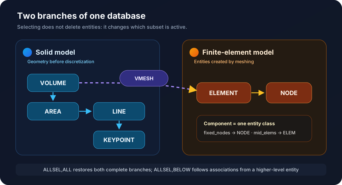
fixed_nodes contains nodes;
mid_elemsElements.
| Physical question | Useful entity | Example APDL |
|---|---|---|
| Where does the solid end up? | Face area or nodes | NSEL,...,LOC,X,... |
| Which part will be embedded? | Nodal component | CM,fixed_nodes,NODE |
| What elements are in the center? | Elements by centroid | ESEL,...,CENT,X,... |
| Which entities are active now? | Selection Status | *GET,...,COUNT |
Selecting does not mean deleting
Both NSEL and ESEL internal flags change. Entities do not
selected remain in the database. The danger is not to lose them, but to forget that they are
temporarily invisible to subsequent commands.
Step 1 — Build the parametric geometry
The M01 block remains:
/PREP7
ET,1,SOLID185
MP,EX,1,young
MP,PRXY,1,nu
TYPE,1
MAT,1

BLOCK,0,beam_l,0,beam_h,0,beam_b
ESIZE,mesh_h
VMESH,ALL
A BLOCK isolated creates a volume delimited by six areas, twelve lines and eight
keypoints. VMESH adds elements and nodes. Your IDs may change even though the solid
represent the exact same beam.
M02 limit: We use very ET, MP, ESIZE and
VMESH as legacy infrastructure. The choice of element and material is
will be justified in M03; the meshing strategy will be studied in M04.
Before reducing any selection, we save the full size of the model:
ALLSEL,ALL
*GET,n_nodes,NODE,0,COUNT
*GET,n_elements,ELEM,0,COUNT
These two values are our baseline. At the end they should reappear exactly.
Step 2 — Think of selections as set algebra
The second command argument xSEL indicates how the new condition is combined
with the active set:
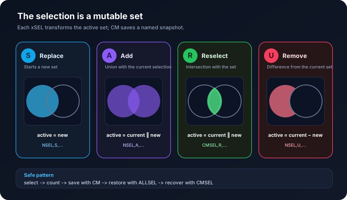
A, R, and U operate on the previous selection state.
| Operation | Reading | Result |
|---|---|---|
S | Select | Replace the active set with a new one. |
A | Additionally select | Add entities: union. |
R | Reselect | Keep the intersection. |
U | Unselect | Withdraw entities: difference. |
That is why a selection sequence must be read from top to bottom. If an operation leaves the set empty, a subsequent reselection cannot retrieve entities that were no longer active.
Step 3 — Control geometric tolerance
A calculated coordinate and a stored coordinate can differ by tiny fractions.
MAPDL uses a tolerance on non-integer value selections. Its automatic logic depends
of VMIN and VMAX; for example, if both are equal and not null, you can take
the 0.5 % requested value
A global selection at X=1.0 m could include a much wider band of the
expected when the mesh is very fine. In a reproducible script it is convenient to declare the criterion:
select_tol=MIN(beam_h,beam_b)*1E-5
SELTOL,select_tol
For the base case, select_tol=5E-7 m. It is small compared to the geometry and sufficient
to absorb numerical noise. Tolerance remains active until redefined, so in the end
we will restore it:
SELTOL,A Tolerance Must Not Equal the Element Size
If you wrote SELTOL,mesh_h, a face selection could also capture the
next node layer. The command would work; the physical region would be incorrect.
Step 4 — Create fixed_nodes
We start in the global Cartesian system and select the face X=0:
CSYS,0
NSEL,S,LOC,X,0
*GET,n_fixed,NODE,0,COUNT
CM,fixed_nodes,NODE
ALLSEL,ALL
The pattern contains four decisions:
NSEL,Sstarts a new nodal set.LOC,X,0expresses the region by a geometric condition.*GETimmediately checks that the selection exists.CMsave a photo before restoring everything withALLSEL.
Order is essential. If you were to execute ALLSEL before CM,
fixed_nodes would contain all nodes.
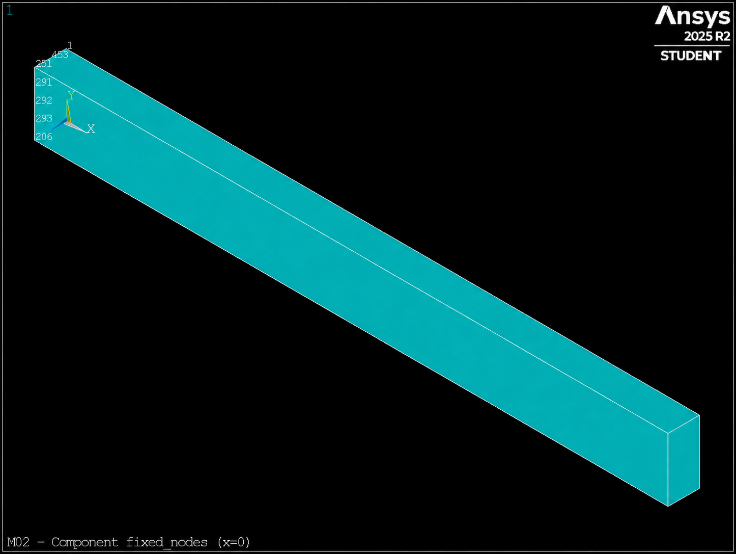
fixed_nodes (CMSEL,S,fixed_nodes + EPLOTregion x=0 Before you Apply D.
Step 5 — Define a local tolerance at the tip
LOCAL defines a coordinate system and CSYS decides which one is active.
Local system numbers must be greater than 10; we will use the 11:
LOCAL,11,CART,beam_l,0,0
CSYS,11
NSEL,S,LOC,X,0
*GET,n_tip,NODE,0,COUNT
CM,tip_nodes,NODE

CSYS,0
ALLSEL,ALL
We have not rotated the shafts; we only translate the origin to X=beam_l. In the system
global, the tip is in X=beam_l. In the 11 system, it is in X=0.
Mental Model: A Ruler Attached to the Part
If beam_l changes, the local origin moves with the tip. The condition
LOC,X,0 remains identical. This idea will be very useful in assembled models,
tilted regions and repetitive operations.
LOC interprets X, Y and Z in the active system. That's why CSYS,0 is not
cosmetic cleanup: it prevents later selections from operating in the wrong coordinate system.
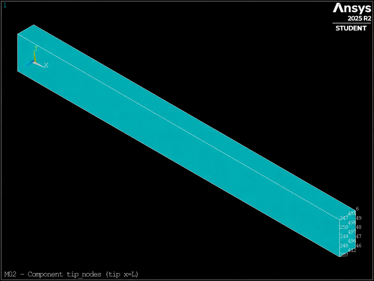
tip_nodes with local coordinate system 11 at the tip.
Step 6 — Create top_nodes and mid_elems
With the global system restored, the top face is defined by its height:
NSEL,S,LOC,Y,beam_h
*GET,n_top,NODE,0,COUNT
CM,top_nodes,NODE
ALLSEL,ALL
For the central band, we change the entity class. ESEL,CENT checks the coordinate
of each element centroid:
ESEL,S,CENT,X,0.4*beam_l,0.6*beam_l
*GET,n_mid_elems,ELEM,0,COUNT
CM,mid_elems,ELEM
ALLSEL,ALL
The band must contain elements, but not all. That relationship is more stable than requiring a number exact count, because it may vary with the meshing strategy or version.
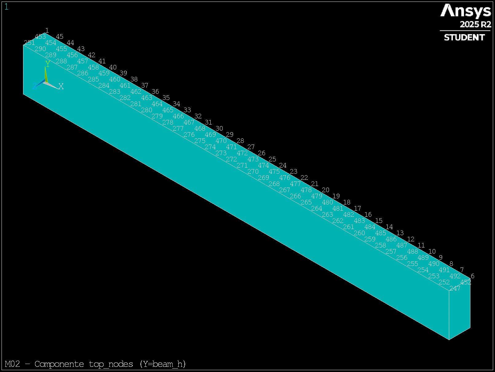
top_nodes on the upper face (Y=beam_h).
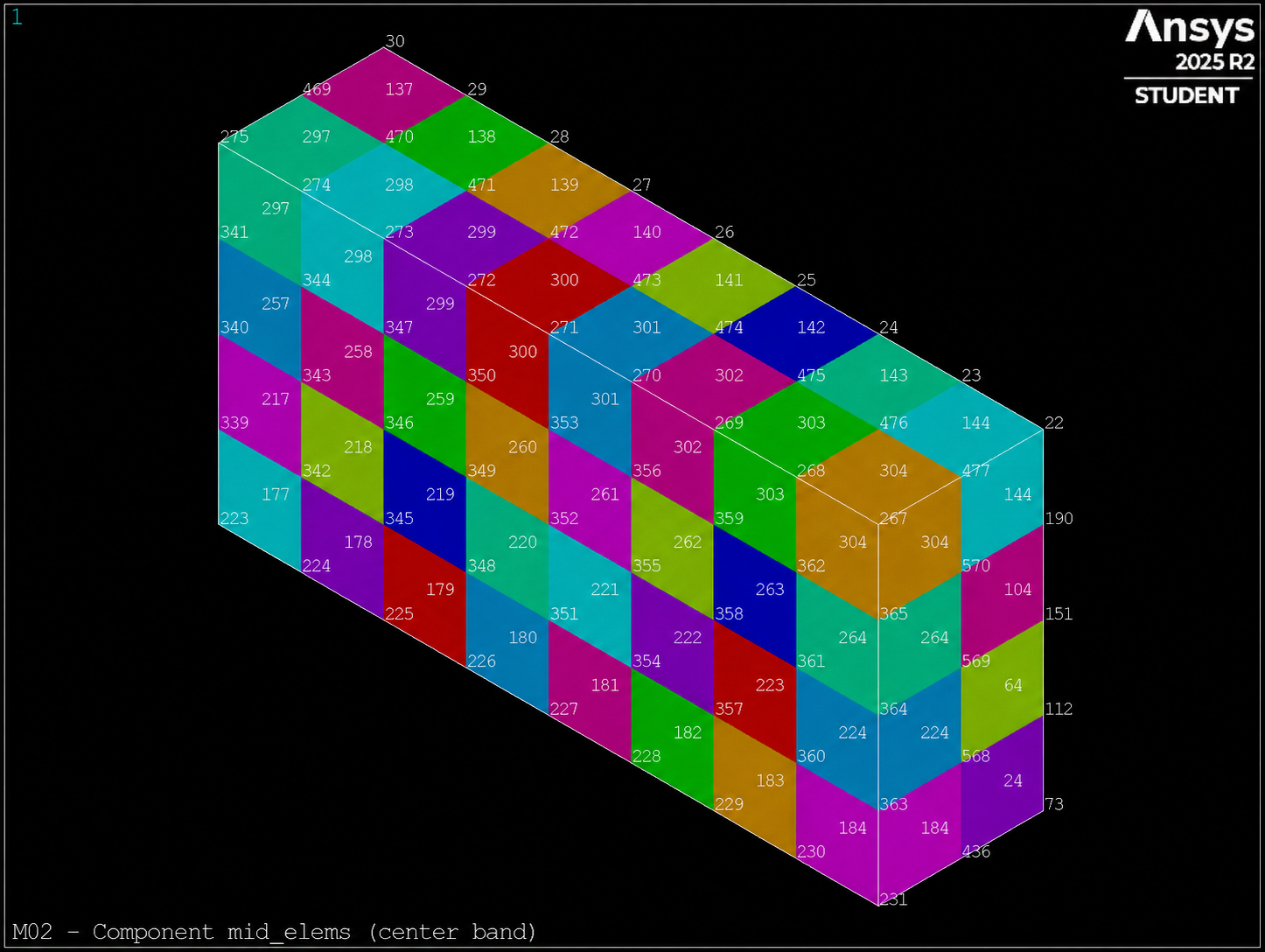
mid_elems (central band 0.4L–0.6L). This component is reused by the M03 EMODIF challenge.
Step 7 — Construct tip_top_nodes via intersection
The top edge of the tip meets two simultaneous conditions: belong to
tip_nodes and to top_nodes.
CMSEL,S,tip_nodes
CMSEL,R,top_nodes
*GET,n_tip_top,NODE,0,COUNT
CM,tip_top_nodes,NODE
ALLSEL,ALL
CMSEL,S retrieves the first component. CMSEL,R intersects it with the
b. The result must be non-empty, less than the full face of the tip and less than all
the top face:
0 < n_tip_top < n_tip
0 < n_tip_top < n_top
Step 8 — Demonstrate that the ends do not overlap
A positive-length beam cannot have nodes belonging to both ends:
CMSEL,S,fixed_nodes
CMSEL,R,tip_nodes
*GET,n_overlap,NODE,0,COUNT
ALLSEL,ALL

*GET,n_restored,NODE,0,COUNT
The expected conditions are:
n_overlap  = 0
n_restored = n_nodes
The first is a physical check. The second is a health check: it confirms that no accidental filters will continue to affect subsequent modules.
Step 9 — Turn regions into an executable contract
A component that exists by name may be empty or contain too much. The deliverable evaluates
all relationships and summarizes the result in passes:
passes=1
*IF,n_fixed,LE,0,THEN
  passes=0
*ENDIF
*IF,n_overlap,NE,0,THEN
  passes=0
*ENDIF
*IF,n_restored,NE,n_nodes,THEN
  passes=0
*ENDIF
Then generate legible evidence:
*CFOPEN,m02_selection_audit,csv
*VWRITE
('case,beam_l,beam_h,mesh_h,n_nodes,n_elements,n_fixed,n_tip,n_top,n_mid_elems,n_tip_top,n_overlap,n_restored,passes')
...
*CFCLOS
Open m02_selection_audit.csv and check that the last column is valid 1.
Exact counts may vary; the relationships recorded in the file
02_expected_results.csv must always be adhered to.
The pattern to keep
Select → count → name → restore → recover → audit
Translated to APDL:
NSEL,S,...
*GET,n_region,NODE,0,COUNT
CM,region_nodes,NODE
ALLSEL,ALL

CMSEL,S,region_nodes
! operation on the region
ALLSEL,ALL
This pattern separates the definition of a region from its use. In M05 we may apply constraints or loads to components whose meaning has already been proven.
Bug hunt
Download 02_bug_hunt.mac.
The file runs, but contains five logical defects:
- A physical region defined by node IDs.
- A component created after restoring all nodes.
- A local system that continues to operate unintentionally.
- A tolerance of the same order as the mesh size.
- A partial selection of elements that propagates to the end.
For each defect, write: incorrect state → probable symptom → check that reveals it → minimum correction. It is not enough to just point to the line.
Verifiable challenge
Open 02_challenge.mac.
The length is now 1.2 m and the mesh size is 0.02 m.
- Create all five components without writing IDs.
- Use local system 11 to define
tip_nodes. - Build
tip_top_nodesby intersection. - Demonstrate that the ends do not overlap.
- Generate
m02_selection_audit.csvwith the same schema as the solution.
Acceptance criteria
- All five components are non-empty.
n_overlap=0.n_tip_top<n_tipandn_tip_top<n_top.0<n_mid_elems<n_elements.n_restored=n_nodes.- The row of the CSV ends with
passes=1. - No node or element ID appears in the selection instructions.
Self-assessment
What is the difference between NSEL and CM?
NSEL modifies the active nodal set; CM saves the selected nodes under a reusable name.
Why should CM run before ALLSEL?
Because CM captures the existing selection at that time. After ALLSEL would save all the nodes.
What does R represent in CMSEL,R,top_nodes?
A reselection: retains only the intersection between the active set and top_nodes.
Why do we restore CSYS,0?
Because you select them by LOC interpret the coordinates in the active system. Forgetting it silently changes the meaning of X, Y and Z.
Why don't we demand an exact number of nodes?
Because it may depend on the mesh maker or the version. We check physical invariants and relationships between sets, which are more robust.
What does n_restored=n_nodes prove?
That ALLSEL,ALL retrieved all nodes and we did not leave an accidental filter active.
Evidence of learning
02_geometry_selections.macexecuted from a clean session.m02_selection_audit.csvwithpasses=1.02_challenge.maccompleted for the beam of1.2 m.- Diagnostic table of the five defects of
02_bug_hunt.mac. - Brief explanation of why a geometric selection is more stable than a list of IDs.
Validation checklist
- I distinguish entities from the solid model and the finite element model.
- I can anticipate the effect of
S,A,RandU. - Explicitly defined and restored
SELTOL. - I created
fixed_nodesandtip_nodeswithout IDs. - Restored
CSYS,0after using the 11 system. - I built
tip_top_nodesas an intersection of two components. - I checked that
fixed_nodesandtip_nodes(non-overlapping) - I verified that
ALLSEL,ALLretrieves all nodes. - The challenge generates a CSV with
passes=1. - I did not apply loads or solve the model in this module.
Technical traceability of M02
Content contrasted with ANSYS mechanical APDL Command Reference 2024 R1:
ALLSEL, CM, CMSEL, CSYS, ESEL,
LOCAL, NSEL and SELTOL; and with chapter 3 of
ANSYS Mechanical APDL Modeling and Meshing Guide.
Next
Your model already recognizes regions by meaning, not by numerical chance. In M03 you will decide what element formulation, material and attributes should the entities you have just build and you'll learn how to audit those assignments.