
You already know how to create a geometry and find regions without relying on IDs. Now it's time to decide what mathematical behavior each element will have and demonstrate that the stored attributes match your intent.
YOUR MISSION
You will build a solid steel beam with SOLID185, you will separate the operations
of defining, activating, and assigning, and you will generate a CSV audit. In the challenge, you will change
only the central band to aluminum without remeshing.
Guiding question: How do you know which material an existing element has?
Objectives
By completing M03 you will be able to demonstrate that:
- You choose between a beam, sheet or solid idealization according to the physical question.
- Justify
SOLID185without claiming that a 3D model is always more accurate. - Distinguish defined tables, active pointers, and stored attributes.
- You define an isotropic elastic material by
EXandPRXY. - Explain when a section is needed and when the geometry already contains it.
- Fix existing attributes with
EMODIF. - Type and material audits using
ESEL,*GETand relationships between counts.
Prerequisites and downloads
- Have completed M02 or know how to create
mid_elemsby centroids. - Maintain consistent SI units: meters, newtons, and pascals.
- Understand that M03 ends in
/PREP7: we will not apply loads or solve yet.
03_start.macStarting point.03_elements_materials.mac— complete solution.03_bug_hunt.mac— five deliberate defects.03_challenge.mac— bi-material challenge.03_expected_results.csv— self-correction contract.
How to use this lesson
| Path | Duration | Coverage |
|---|---|---|
| First win | 30–35 min | Idealization, defining attributes and meshing with basic audit. |
| Complete | 70–75 min | In addition, correction with EMODIF, bi-material challenge and CSV contract. |
Recommendation: never rely on the active pointer to demonstrate attributes. Count what was stored in each element.
Session map
- Mission: objectives, downloads and idealization prediction.
- Mental models define versus enable attributes.
- Demonstration: ET, MP, meshing and element audit.
- Error hunting: misleading pointers and mixed materials.
- Challenge: bimaterial beam with full partition.
- Mastery: final test that records demonstrated mastery and recommends M04.
Before you code — Predict
Suppose you run these instructions after meshing the entire beam with material 1:
MAT,2
ALLSEL,ALL
Do existing elements become aluminium? No. MAT,2
changes the material that subsequent elements will receive. It does not rewrite existing elements.
This distinction will be the common thread of the lesson.
Physical Model — Choosing Idealization
The same part can be represented by an axis, a midsurface, or its volume. Each reduction retains some information and discards other information. The most complex element is not automatically the most correct: the appropriate idealization is the simplest that answers reliably to the engineering question.
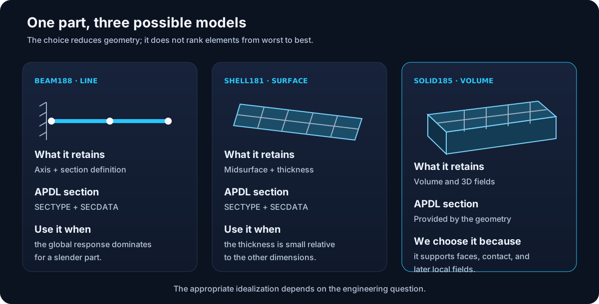
| Element | Representing | Nodal Degrees of Freedom | Section |
|---|---|---|---|
BEAM188 | Line 3D | 3 translations + 3 rotations; optional warp | It is defined with section commands. |
SHELL181 | Midsurface | 3 translations + 3 rotations | Thickness and layers defined through a section. |
SOLID185 | Volume 3D | 3 translations | The shape of the volume provides the section. |
Why we use SOLID185
SOLID185 is a solid structural element of eight nodes and three displacements
per node. We chose it because the running example will later need faces to
apply pressures, inspect local fields, and model possible interfaces. It also keeps visible the relationship between
volume, elements and nodes that you learned in M02.
A didactic decision is not a universal rule
For the overall displacement of a slender beam, BEAM188 can be more efficient
and appropriate. A solid 3D demands proper resolution of its mesh and boundary conditions.
M04 will study that responsibility.
Sections: When they appear
A line or surface alone does not contain all the transverse geometry:
! Conceptual beam example
ET,2,BEAM188
SECTYPE,1,BEAM,RECT
SECDATA,beam_b,beam_h
TYPE,2
SECNUM,1

! Conceptual shell example
ET,3,SHELL181
SECTYPE,2,SHELL
SECDATA,thickness
TYPE,3
SECNUM,2
SECTYPE starts the definition, SECDATA provides their data and
SECNUM activates the number for subsequent elements. In our
BLOCK, width and height are already part of the volume; adding an additional section
for SOLID185 does not add physical information.
APDL Model — Defining Is Not Activating
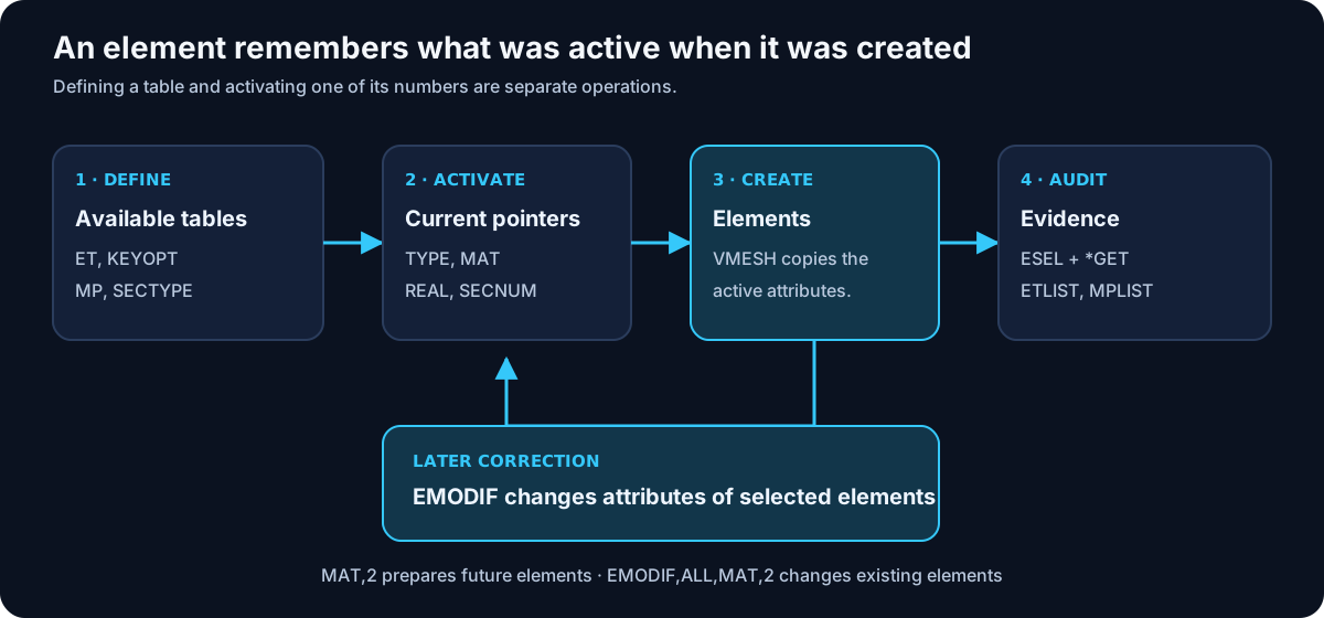
| Action | commands | What changes: |
|---|---|---|
| Definition | ET, KEYOPT, MP, SECTYPE | Tables available in the database. |
| Enabled | TYPE, MAT, SECNUM | Pointers used in the next creation. |
| Assign on Create | VMESH | Attributes copied to new elements. |
| Modify | EMODIF | Attributes of elements that already exist. |
| Audit | ESEL, *GET, ETLIST, MPLIST | Evidence of the assigned attributes. |
Step 1 — Define the Element Type
ET,1,SOLID185
KEYOPT,1,2,0
ET,1,SOLID185 saves the formulation under type number 1.
KEYOPT,1,2,0 makes explicit the complete integration formulation with B-bar,
which is the default option. Writing the default value documents the intent;
it does not mean that the other options are interchangeable without study.
Step 2 — Define Isotropic Materials
young_steel=210E9
nu_steel=0.30
young_aluminum=70E9
nu_aluminum=0.33

MP,EX,1,young_steel
MP,PRXY,1,nu_steel
MP,EX,2,young_aluminum
MP,PRXY,2,nu_aluminum
Isotropic linear elasticity requires Young's modulus EX and Poisson's ratio
PRXY. The number after the property is the material ID, not a unit.
In the SI system of the course, 210E9 represents 210 GPa.
/UNITS doesn't convert your numbers
/UNITS,SI records the chosen system, but does not transform 210000
into 210E9. Dimensional consistency remains the responsibility of the script.
Step 3 — Activate and mesh
TYPE,1
MAT,1

BLOCK,0,beam_l,0,beam_h,0,beam_b
ESIZE,mesh_h
VMESH,ALL
Just before VMESH, the pointers say, “the next elements will be type 1
and material 1.” During meshing, each element stores those numbers. Defining material 2 does not
assign it to anything yet.
M03 Limit: ESIZE and VMESH remain
infrastructure. M04 will justify size, local controls, quality and convergence.
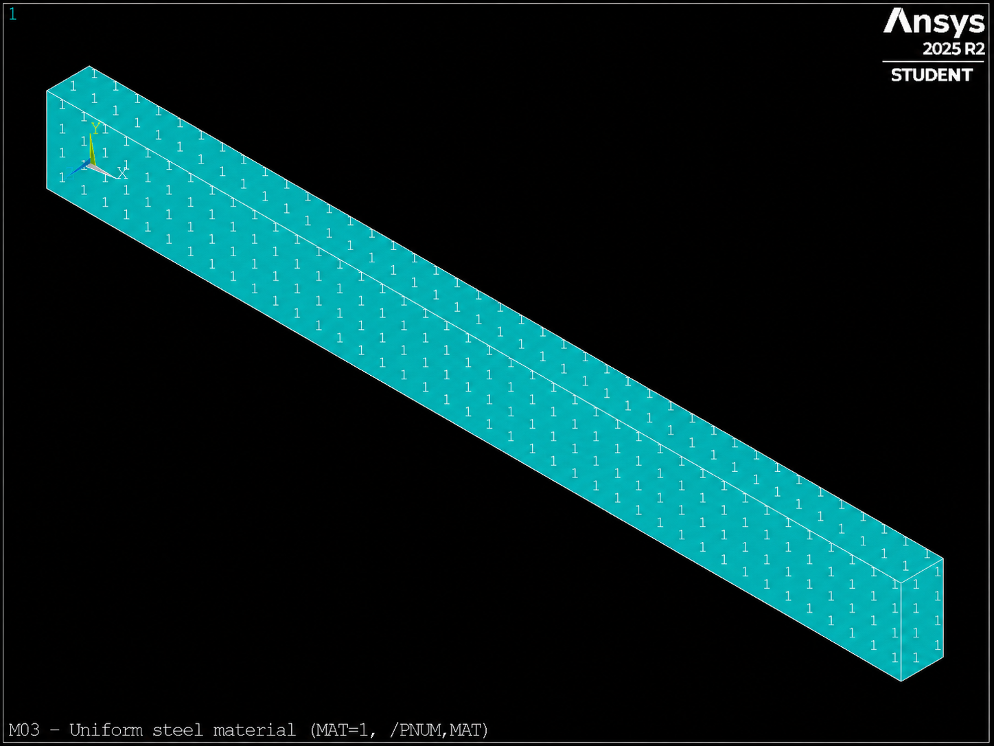
MAT=1) visible with /PNUM,MAT as a result of VMESH.
Step 4 — Prepare the center band
ALLSEL,ALL
ESEL,S,CENT,X,0.4*beam_l,0.6*beam_l
CM,mid_elems,ELEM
*GET,n_mid_elems,ELEM,0,COUNT
ALLSEL,ALL
We reused the robust pattern of M02. The component does not depend on IDs and will be the exact scope of the challenge modification.
Step 5 — Audit elements, not pointers
*GET,n_elements,ELEM,0,COUNT

ESEL,S,TYPE,,1
*GET,n_type1,ELEM,0,COUNT
ALLSEL,ALL

ESEL,S,MAT,,1
*GET,n_mat1,ELEM,0,COUNT
ALLSEL,ALL

ESEL,S,MAT,,2
*GET,n_mat2,ELEM,0,COUNT
ALLSEL,ALL
ESEL,S,MAT,,2 asks which elements store material 2. It does not ask which
material is active. The base case passes only if:
n_type1 = n_elements
n_mat1  = n_elements
n_mat2  = 0
0 < n_mid_elems < n_elements
ETLIST,1 and MPLIST,ALL complement the audit: they show the
definitions, while counts demonstrate assignments.
Step 6 — Correct an Existing Assignment
In the challenge, the correct sequence preserves the selected scope:
CMSEL,S,mid_elems
EMODIF,ALL,MAT,2
ALLSEL,ALL
Here ALL means all selected elements. Therefore,
ALLSEL,ALL must come afterward. If you run it first, you will change the entire beam.
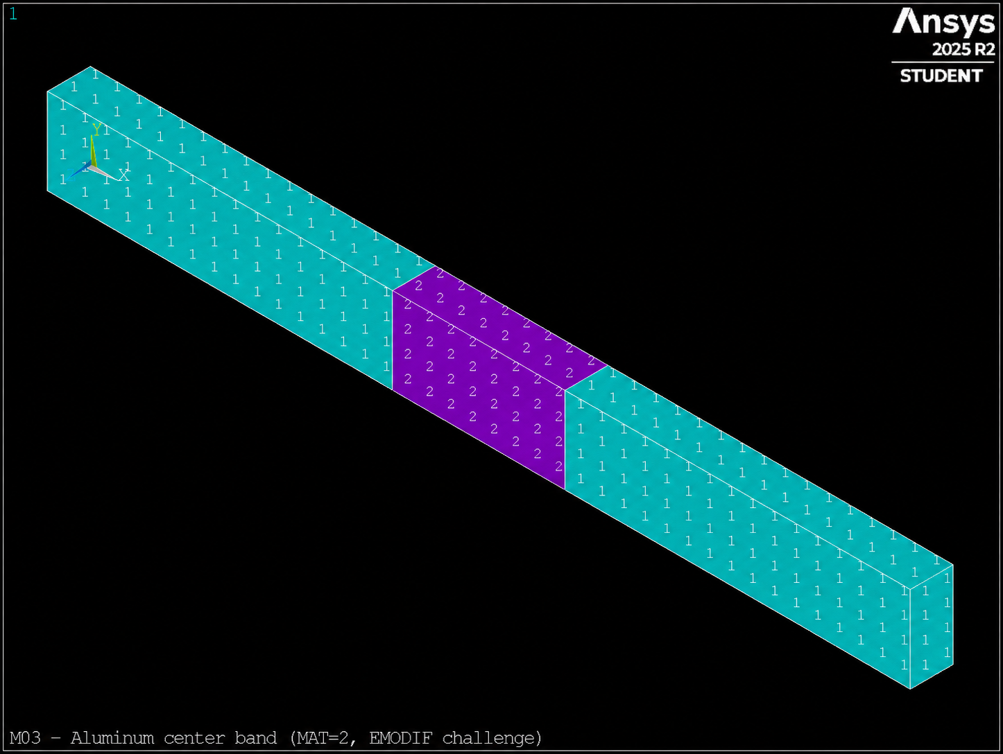
MAT=2) after EMODIF is applied to mid_elems.
CSV contract
03_elements_materials.mac generates m03_attribute_audit.csv:
case,n_elements,n_type1,n_mat1,n_mat2,n_mid_elems,young_steel,young_aluminum,young_ratio,passes
We do not set an exact number of elements because it may vary with the mesher or version.
Relationships do express the intent of the model. In the base case,
passes=1 demands that everything be steel; in the challenge, the band must be aluminum and the
modulus ratio must equal 3.
Reusable pattern
! 1. Define
ET,type_id,element_name
MP,EX,material_id,young

! 2. Activate
TYPE,type_id
MAT,material_id

! 3. Create
VMESH,ALL

! 4. Audit
ESEL,S,MAT,,material_id
*GET,n_assigned,ELEM,0,COUNT
ALLSEL,ALL
Bug hunt
Run 03_bug_hunt.mac. It does not target fatal errors: it contains five
plausible decisions that produce a model different from the stated intent. For each one, write:
symptom, cause, test and correction.
- Check the steel elastic modulus units.
- Identify which material was active during
VMESH. - Explain your answer.
SECNUM,1does not create a section and is left over in this solid. - Locate where the scope of
mid_elemsis lost. - Demonstrate why
MAT,1does not repair existing elements.
Verifiable challenge — Bi-material beam
Complete 03_challenge.mac. The region 0.4L ≤ X ≤ 0.6L will be aluminum
and the rest steel. Do not mesh again, do not use IDs and do not enter /SOLU.
| Test | Criterion | Meaning |
|---|---|---|
| Type | n_type1=n_elements | The formulation did not change. |
| Band | n_mat2=n_mid_elems | Only the component received aluminum. |
| Partition | n_mat1+n_mat2=n_elements | There is no shortage or excess of elements. |
| Two materials | n_mat1>0 and n_mat2>0 | The challenge did not degenerate into a homogeneous case. |
| Properties | young_ratio=3 | Inputs are consistent. |
| Result | passes=1 | All tests passed. |
Self-assessment
- What is the difference between
MP,EX,2,70E9andMAT,2? - Why does querying the active pointer not demonstrate the material assigned to existing elements?
- What information does a section add to
BEAM188? - Why do we not add
SECNUMto the homogeneous solid? - What happens if you run
ALLSEL,ALLbeforeEMODIF,ALL,MAT,2?
View Short Answers
- The first defines a property of material 2; the second activates that ID for future element creation.
- Because the pointer and stored attributes are distinct states.
- The transverse geometry that a line does not contain.
- The section is already represented by the dimensions of the volume.
- The entire selected model is modified, not only the central band.
Evidence of learning
Keep in your work folder:
m03_attribute_audit.csvof the base case withpasses=1.- The CSV of the challenge with both materials present and the central band correctly assigned.
- A screenshot or text excerpt from
ETLIST,1andMPLIST,ALL. - Your diagnosis of the five defects of
03_bug_hunt.mac. - A technical sentence justifying why
SOLID185is used in this course.
Exit checklist
- ☐ I can distinguish beam, sheet and solid model.
- ☐ I know which commands define tables and which ones activate pointers.
- ☐ I understand when
VMESHcopies the attributes. - ☐ I can change existing elements with
EMODIF. - ☐ I audit TYPE and MAT through counts, not visual appearance.
- ☐ My base case and challenge generate a reproducible CSV.
- ☐ I have not applied loads or solved the model.
Technical traceability
This lesson builds on ANSYS mechanical APDL Element Reference for
BEAM188, SHELL181 and SOLID185;
Material Reference for isotropic linear elasticity; and
Command Reference 2024 R1 for the commands presented.
Next step: M04
We already know what elements we have created and what properties they possess. In M04 we will no longer accept an element size out of habit: we will measure quality and sensitivity to justify the mesh.