
A mesh does not define where the structure is supported or which external loads it must carry. In M05 we will turn the free-body diagram into constraints and loads, then check the values stored by MAPDL before solving.
Your mission
You will fully constrain the left end of the beam, distribute a total force of
-1000 N over its right end, and generate a CSV that records the selected regions,
constrained degrees of freedom, and actual sum of nodal forces.
Guiding question: How do you distinguish a total force from a force applied to each node?
Objectives
By completing M05 you will be able to demonstrate that:
- Translate a free-body diagram into regions, degrees of freedom, and force components.
- Apply constraints and loads exclusively on named components.
- Explain what each
ALLmeans inD,ALL,ALL,0. - Maintain a constant resultant force when the number of nodes changes.
- Distinguish selection, nodal system, visualization and results system.
- Read constraints and stored forces using
*GET. - Audit boundary conditions without using reactions or results.
Prerequisites and downloads
- Complete M02 to work with components and selections.
- Complete M04; we will use the first accepted mesh, with 40 elements.
- Remember that
SOLID185has the displacement DOFsUX,UY, andUZ.
05_start.mac— starting point.05_loads_constraints.mac— audited solution.05_bug_hunt.mac— five deliberate failures.05_challenge.mac— mesh independence challenge.05_expected_results.csv— self-checking contract.
How to use this lesson
| Track | Duration | Scope |
|---|---|---|
| Quick win | 30–35 min | Prediction, regions, fixed support and audited load distribution. |
| Complete | 65–70 min | In addition, reference systems, sum of forces, challenge with more nodes. |
Recommendation: run DLIST and FLIST before SOLVE. The intent of the script does not prove
what conditions were actually stored.
Session map
- Mission: objectives, downloads, and a refinement prediction.
- Mental model: boundary conditions as part of the model.
- Demo: apply, list, and audit loads and constraints.
- Bug hunting: empty selections and incorrect load distributions.
- Challenge: same total force with more nodes loaded.
- Mastery: final test that records demonstrated mastery and recommends M06.
Prediction — The error that grows as you refine
The base mesh has six nodes at the tip. What would be the total force if you executed
F,ALL,FY,-1000 with those six nodes selected?
6 nodes × (−1000 N/node) = −6000 N
F takes a nodal load. MAPDL does not interpret -1000 as the
resultant that you intend to distribute. That intent must be explicit in the script.
From a physical diagram to a test
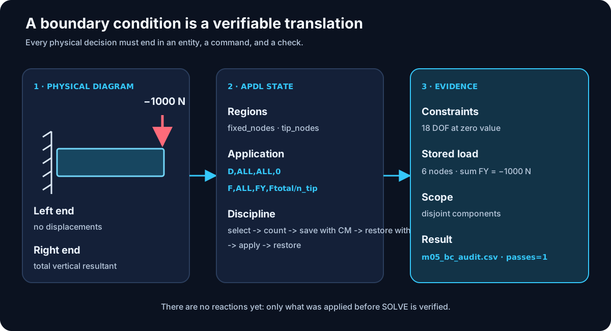
| Physical decision | APDL Representation | Test |
|---|---|---|
| Fixed left end | fixed_nodes + D | 6 nodes and 18 zero displacements. |
| Total vertical force | tip_nodes + F | 6 nodes loaded and sum FY=-1000 N. |
| Different regions | Component intersection | n_overlap=0. |
Mental model — Boundary conditions are part of the model
An ideal fixed support is not simply “where the part touches a wall.” It is the mathematical assumption that specific degrees of freedom have prescribed values. A nodal force is not merely a decorative arrow either: it has a magnitude, sign, direction, point of application, and reference system.
A solution can converge with wrong conditions
The solver can easily solve a completely blocked beam or a load six times greater than intended. Algebraic convergence does not correct the physical model.
Step 1 — Recover the mesh chosen in M04
We use mesh_h=0.05 m because it was the first mesh to meet the M04
displacement criterion. Its divisions are 20 × 2 × 1:
MSHAPE,0,3D
MSHKEY,1
! LESIZE on the three line families
VMESH,ALL

*GET,n_nodes,NODE,0,COUNT
*GET,n_elements,ELEM,0,COUNT
The M05 entry contract requires 126 nodes and 40 elements.
Step 2 — Build regions before applying anything
SELTOL,select_tol
CSYS,0

NSEL,S,LOC,X,0
CM,fixed_nodes,NODE
*GET,n_fixed,NODE,0,COUNT
ALLSEL,ALL

NSEL,S,LOC,X,beam_l
CM,tip_nodes,NODE
*GET,n_tip,NODE,0,COUNT
ALLSEL,ALL

SELTOL,
Selection and application are separate operations. We first show that each region exists; then we store its meaning in a component. The intersection test confirms that no node belongs simultaneously to both ends.
Step 3 — Enter /SOLU without solving
FINISH
/SOLU
M05 enters the solution processor because loads are part of the analysis definition.
However, it contains neither ANTYPE nor SOLVE. At the end, we will
have a prepared database, but no reactions, result sets, or stresses.
Step 4 — Apply the fixed support
CMSEL,S,fixed_nodes
D,ALL,ALL,0
ALLSEL,ALL
The line should be read with its two occurrences of ALL:
- the first
ALLmeans all currently selected nodes; - the second means all the active degrees of freedom of the element.
For SOLID185, those degrees of freedom are UX, UY, and
UZ. No rotations appear because the solid element does not have them as degrees of
nodal freedom.
Step 5 — Distribute a resultant
CMSEL,S,tip_nodes
*GET,n_tip,NODE,0,COUNT
force_per_node=tip_force/n_tip
F,ALL,FY,force_per_node
ALLSEL,ALL
For six nodes, force_per_node=-166.6667 N. The parameter expresses a fundamental
distinction:
physical input:      tip_force
input to F:         force_per_node
final check:        sum of all stored FY forces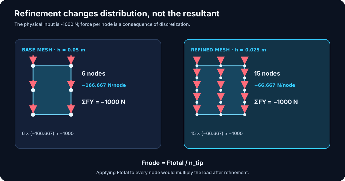
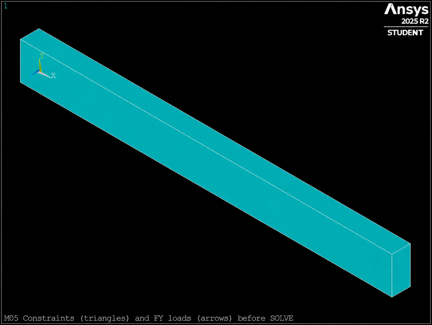
/PSF,BC + EPLOT) before SOLVE. The resultant ΣFY=−1000 N is verified in the CSV, not by this image.
Safety pattern
CMSEL,S,nombre_region
*GET,n_region,NODE,0,COUNT
! abort or fail if n_region=0
comando_de_carga
ALLSEL,ALL
Select, check, apply, and restore form a single unit. Separating those steps with long blocks of code makes it easier for an incomplete selection to propagate.
Reference systems — Four different concepts
| Status | What controls | What does not control |
|---|---|---|
CSYS | Interpretation of coordinates and geometric selections. | It does not retroactively rotate an existing nodal force. |
| Nodal system | Directions of UX/UY/UZ and FX/FY/FZ. | It does not change when only the view is modified. |
DSYS | System used to display geometry. | It does not redefine loads or constraints. |
RSYS | Postprocessing result system. | It does not act on the applied loads. |
In the working example, all nodal systems remain global Cartesian. That is why
FY unambiguously represents the global Y direction. Loads in systems
rotated nodal systems require an explicit decision, not a cosmetic display change.
F vs. SF
| Command | Entrance | Typical use |
|---|---|---|
F | Concentrated force per node. | Distributed resultant or nodal actions. |
SF | Surface load on faces identified by nodes. | Normal pressure, convection, or other compatible labels. |
! Conceptual example, not added to the running example
CMSEL,S,top_nodes
SF,ALL,PRES,pressure_value
SFLIST,ALL,PRES
ALLSEL,ALL
Pressure follows the face-normal convention; it does not automatically replace our transverse tip force. M05 retains a single load so that the audit remains unambiguous.
Step 6 — Listing is not yet automating
DLIST,ALL,ALL
FLIST,ALL,ALL
Listings allow you to read nodes, labels and values in the file .out. They are
essential for debugging, but a human review is not enough to run many cases.
We will convert the same questions into approval parameters and conditions.
Step 7 — Audit the three prescribed displacements
CMSEL,S,fixed_nodes
node_id=0

*DO,j,1,n_fixed
  node_id=NDNEXT(node_id)
  *GET,dof_ux,NODE,node_id,D,UX
  *GET,dof_uy,NODE,node_id,D,UY
  *GET,dof_uz,NODE,node_id,D,UZ
  ! check all three values
*ENDDO
NDNEXT returns the next selected node. This lets us traverse the actual IDs
without assuming that they are consecutive. Each of the six nodes must store three zero values:
n_constrained_dof=18.
Checked Compatibility: MAPDL 2025 R2 may return zero when querying
an unconstrained displacement. That is why the macro audits values on
fixed_nodes and uses the global DLIST output to document that there are no
constraints outside the component. It does not attempt to detect absence using a sentinel value.
Step 8 — Sum the forces stored in the model
ALLSEL,ALL
node_id=0
*DO,j,1,n_nodes
  node_id=NDNEXT(node_id)
  *GET,node_fx,NODE,node_id,F,FX
  *GET,node_fy,NODE,node_id,F,FY
  *GET,node_fz,NODE,node_id,F,FZ
  force_sum_x=force_sum_x+node_fx
  force_sum_y=force_sum_y+node_fy
  force_sum_z=force_sum_z+node_fz
*ENDDO
This sum runs through the entire model, not just tip_nodes. Therefore it can detect
an accidental force outside the expected region or an unexpected component.
load_error=ABS(force_sum_y-tip_force)/ABS(tip_force)The audit requires:
n_force_nodes = n_tip
force_sum_x   = 0
force_sum_y   = -1000
force_sum_z   = 0
load_error    < 0.001
CSV contract
05_loads_constraints.mac generates:
case,mesh_h,n_nodes,n_elements,n_fixed,n_tip,n_constrained_dof,n_force_nodes,force_per_node,force_sum_x,force_sum_y,force_sum_z,target_force,load_error,passes
The base row must contain 126 nodes, 40 elements, 18 constraints, 6 loaded nodes, and
passes=1. In MAPDL 2025 R2 the validated sum is -1000 N with an error
on the order of 10⁻¹⁶.
Bug hunting
Run 05_bug_hunt.mac. It does not contain a solver failure; it contains five
logically incorrect implementations.
fixed_nodesis created after all nodes are restored.- The fixed support ends up applied to the entire model.
NSEL,Rtries to find the tip within a selection that no longer contains it.- Full force is applied to each tip node.
CSYS,DSYS, andRSYSare used as if they rotated the nodal system.
Verifiable challenge — Same force, more nodes
Complete 05_challenge.mac with mesh_h=0.025 m. Do not copy case IDs
from the previous case, and do not solve.
| Magnitude | Base case | Challenge |
|---|---|---|
| Elements | 40 | 320 |
| Nodes | 126 | 615 |
| Nodes per end | 6 | 15 |
| Constrained DOFs | 18 | 45 |
| Nodal force | −166.6667 N | −66.6667 N |
| Sum FY | −1000N | −1000N |
Before running, predict which columns should change and which should remain unchanged.
Then explain why force_per_node is not a separate physical input.
Self-assessment
- What are the two meanings of
ALLinD,ALL,ALL,0? - Why does
F,ALL,FY,tip_forcenot apply a total resultant? - What changes when you run
DSYS,1? - Why does the force audit go through all nodes?
- What evidence cannot yet exist before
SOLVE?
See short answers
- All selected nodes and all their active DOF.
- Because
Fapplies the specified value to every selected node. - Only the graphical representation system.
- To detect accidental loads outside the intended component.
- Reactions, equilibrium and structural results.
Evidence of learning
m05_bc_audit.csvwithpasses=1.- The extracts from
DLISTandFLIST. - A screenshot of the constraint and load symbols.
- The CSV of the challenge with the same total force and 15 nodes loaded.
- The diagnosis of the five defects.
Exit checklist
- ☐ My components are created before applying conditions.
- ☐ I check that the regions are non-empty and disjoint.
- ☐ I distinguish total force and force per node.
- ☐ I restore the selection after each application.
- ☐ I do not confuse CSYS, nodal system, DSYS and RSYS.
- ☐ I read and sum the loads stored throughout the model.
- ☐ My script ends without ANTYPE, SOLVE, /POST1 or FSUM.
Technical traceability
The lesson uses Basic Analysis Guide for the definition of boundary conditions
and Command Reference 2024 R1 for D, F, SF,
DLIST, FLIST, NDNEXT, *GET,
CSYS, DSYS and RSYS.
Next step: M06
We have already demonstrated which loads and constraints enter the analysis. In M06 we will define a static analysis, solve it, and compare the applied forces with the reactions to close the global equilibrium audit.