
Step 1 — Recover the mesh chosen in M04
We use mesh_h=0.05 m because it was the first mesh to meet the M04
displacement criterion. Its divisions are 20 × 2 × 1:
MSHAPE,0,3D
MSHKEY,1
! LESIZE on the three line families
VMESH,ALL

*GET,n_nodes,NODE,0,COUNT
*GET,n_elements,ELEM,0,COUNT
The M05 entry contract requires 126 nodes and 40 elements.
Step 2 — Build regions before applying anything
SELTOL,select_tol
CSYS,0

NSEL,S,LOC,X,0
CM,fixed_nodes,NODE
*GET,n_fixed,NODE,0,COUNT
ALLSEL,ALL

NSEL,S,LOC,X,beam_l
CM,tip_nodes,NODE
*GET,n_tip,NODE,0,COUNT
ALLSEL,ALL

SELTOL,
Selection and application are separate operations. We first show that each region exists; then we store its meaning in a component. The intersection test confirms that no node belongs simultaneously to both ends.
Step 3 — Enter /SOLU without solving
FINISH
/SOLU
M05 enters the solution processor because loads are part of the analysis definition.
However, it contains neither ANTYPE nor SOLVE. At the end, we will
have a prepared database, but no reactions, result sets, or stresses.
Step 4 — Apply the fixed support
CMSEL,S,fixed_nodes
D,ALL,ALL,0
ALLSEL,ALL
The line should be read with its two occurrences of ALL:
- the first
ALLmeans all currently selected nodes; - the second means all the active degrees of freedom of the element.
For SOLID185, those degrees of freedom are UX, UY, and
UZ. No rotations appear because the solid element does not have them as degrees of
nodal freedom.
Step 5 — Distribute a resultant
CMSEL,S,tip_nodes
*GET,n_tip,NODE,0,COUNT
force_per_node=tip_force/n_tip
F,ALL,FY,force_per_node
ALLSEL,ALL
For six nodes, force_per_node=-166.6667 N. The parameter expresses a fundamental
distinction:
physical input:      tip_force
input to F:         force_per_node
final check:        sum of all stored FY forces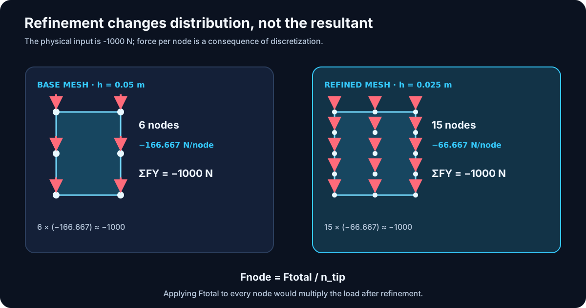
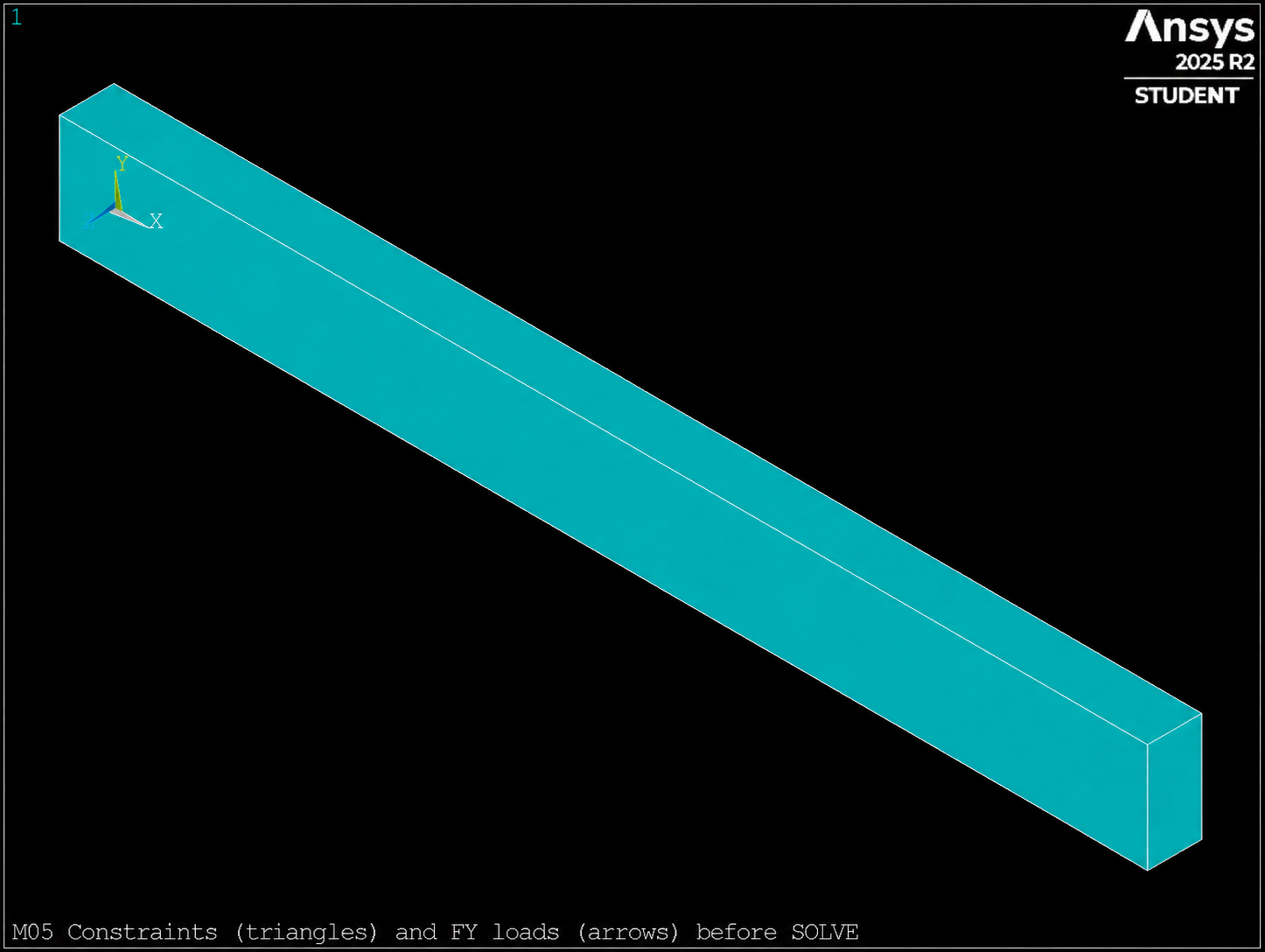
/PSF,BC + EPLOT) before SOLVE. The resultant ΣFY=−1000 N is verified in the CSV, not by this image.
Safety pattern
CMSEL,S,nombre_region
*GET,n_region,NODE,0,COUNT
! abort or fail if n_region=0
comando_de_carga
ALLSEL,ALL
Select, check, apply, and restore form a single unit. Separating those steps with long blocks of code makes it easier for an incomplete selection to propagate.
Reference systems — Four different concepts
| Status | What controls | What does not control |
|---|---|---|
CSYS | Interpretation of coordinates and geometric selections. | It does not retroactively rotate an existing nodal force. |
| Nodal system | Directions of UX/UY/UZ and FX/FY/FZ. | It does not change when only the view is modified. |
DSYS | System used to display geometry. | It does not redefine loads or constraints. |
RSYS | Postprocessing result system. | It does not act on the applied loads. |
In the working example, all nodal systems remain global Cartesian. That is why
FY unambiguously represents the global Y direction. Loads in systems
rotated nodal systems require an explicit decision, not a cosmetic display change.
F vs. SF
| Command | Entrance | Typical use |
|---|---|---|
F | Concentrated force per node. | Distributed resultant or nodal actions. |
SF | Surface load on faces identified by nodes. | Normal pressure, convection, or other compatible labels. |
! Conceptual example, not added to the running example
CMSEL,S,top_nodes
SF,ALL,PRES,pressure_value
SFLIST,ALL,PRES
ALLSEL,ALL
Pressure follows the face-normal convention; it does not automatically replace our transverse tip force. M05 retains a single load so that the audit remains unambiguous.