
Step 4 — Create fixed_nodes
We start in the global Cartesian system and select the face X=0:
CSYS,0
NSEL,S,LOC,X,0
*GET,n_fixed,NODE,0,COUNT
CM,fixed_nodes,NODE
ALLSEL,ALL
The pattern contains four decisions:
NSEL,Sstarts a new nodal set.LOC,X,0expresses the region by a geometric condition.*GETimmediately checks that the selection exists.CMsave a photo before restoring everything withALLSEL.
Order is essential. If you were to execute ALLSEL before CM,
fixed_nodes would contain all nodes.
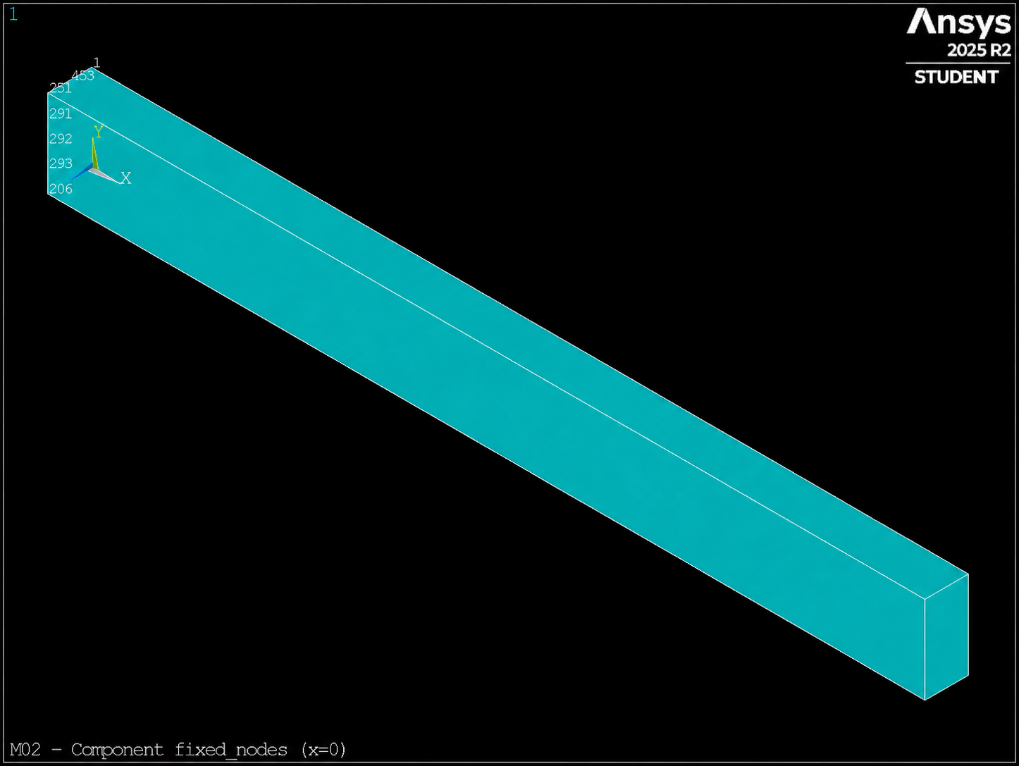
fixed_nodes (CMSEL,S,fixed_nodes + EPLOTregion x=0 Before you Apply D.
Step 5 — Define a local tolerance at the tip
LOCAL defines a coordinate system and CSYS decides which one is active.
Local system numbers must be greater than 10; we will use the 11:
LOCAL,11,CART,beam_l,0,0
CSYS,11
NSEL,S,LOC,X,0
*GET,n_tip,NODE,0,COUNT
CM,tip_nodes,NODE

CSYS,0
ALLSEL,ALL
We have not rotated the shafts; we only translate the origin to X=beam_l. In the system
global, the tip is in X=beam_l. In the 11 system, it is in X=0.
Mental Model: A Ruler Attached to the Part
If beam_l changes, the local origin moves with the tip. The condition
LOC,X,0 remains identical. This idea will be very useful in assembled models,
tilted regions and repetitive operations.
LOC interprets X, Y and Z in the active system. That's why CSYS,0 is not
cosmetic cleanup: it prevents later selections from operating in the wrong coordinate system.
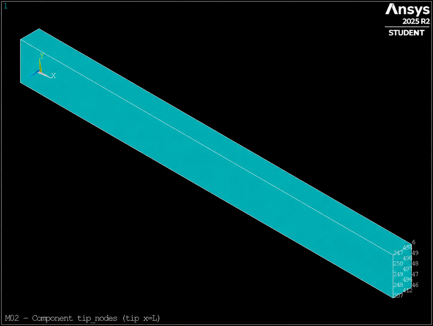
tip_nodes with local coordinate system 11 at the tip.
Step 6 — Create top_nodes and mid_elems
With the global system restored, the top face is defined by its height:
NSEL,S,LOC,Y,beam_h
*GET,n_top,NODE,0,COUNT
CM,top_nodes,NODE
ALLSEL,ALL
For the central band, we change the entity class. ESEL,CENT checks the coordinate
of each element centroid:
ESEL,S,CENT,X,0.4*beam_l,0.6*beam_l
*GET,n_mid_elems,ELEM,0,COUNT
CM,mid_elems,ELEM
ALLSEL,ALL
The band must contain elements, but not all. That relationship is more stable than requiring a number exact count, because it may vary with the meshing strategy or version.
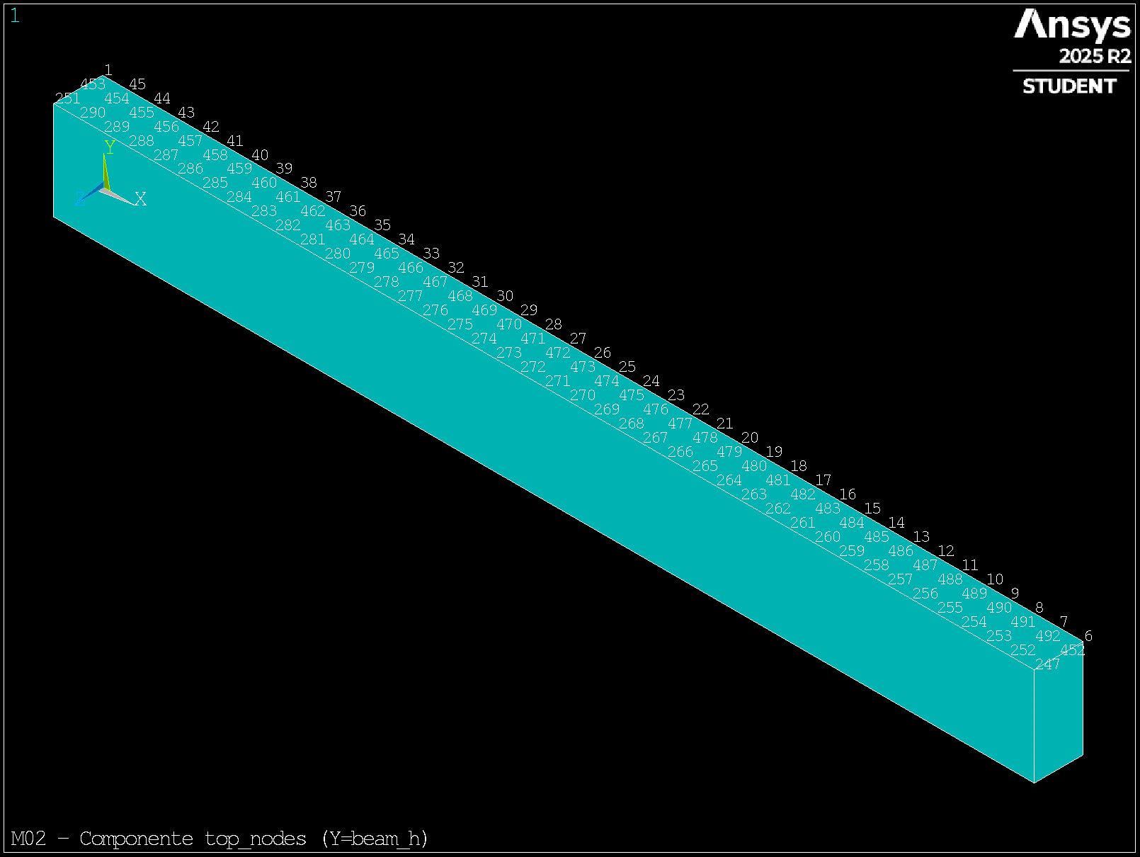
top_nodes on the upper face (Y=beam_h).
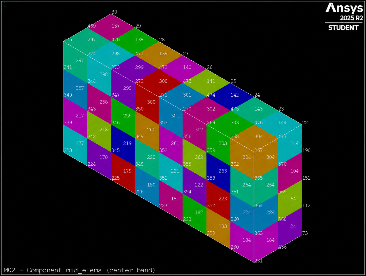
mid_elems (central band 0.4L–0.6L). This component is reused by the M03 EMODIF challenge.